logo
Products
PRODUCTS DETAILS
Home > Products >
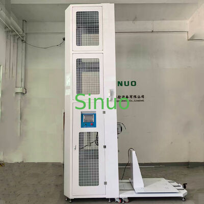
IEC 61851-1 Electric Vehicle Conductive Charging System IK Code Test Equipment

IEC 61851-1 Electric Vehicle Conductive Charging System IK Code Test Equipment

MOQ: 1
Price: Negotiable
Standard Packaging: Plywood Case
Delivery Period: 30 Days
Payment Method: T/T
Supply Capacity: 20 Sets Per Month
Detail Information
Place of Origin
China
Brand Name
Sinuo
Certification
Calibration Certificate (Cost Additional)
Model Number
SNQC1008B
Impact Energy:
5, 20J
Equivalent Mass:
1.7 Kg, 5 Kg ± 1%
Height Range:
200–2500 Mm
Swing Tube Length:
1000 Mm
Tube Diameter:
15.9 Mm
Release Method:
Electromagnetic Release
Drop Height:
0–500 Mm
Lifting Method:
Motorized
Impact Height:
300 - 2000mm
Highlight:

Conductive Charging Test Equipment

,

IEC 61851-1 Test Equipment

,

IK Code Test Equipment

Product Description
IEC 61851-1 Electric Vehicle Conductive Charging System IK Code Test Equipment
Applied Standards & Clauses
  • IEC60068-2-75:2014 Environmental testing - Part 2-75: Tests - Test Eh: Hammer tests
  • IEC62262:2021 Degrees of protection provided by enclosures for electrical equipment against external mechanical impacts (IK code)
  • IEC 61851-1-2017 Electric vehicle conductive charging system - Part 1: General requirements 12.11
  • IEC 62477-1:2022 Safety requirements for power electronic converter systems and equipment - Part 1: General 5.2.2.4.3
  • Clause 5.19 of NB/T33008.1-2018, Clause 7.15 of NB/T33001-2018, Clause 7.11 of NB/T33002-2018, and Article 10.2.701.2 of IEC 62439-7:2022
Purpose, Equipment Principle and Structure

This equipment is used for conducting mechanical strength tests on electric vehicle charging piles or distribution cabinets for charging vehicles.

According to test Eha: The pendulum and impact element are released freely through a 1-meter pendulum tube at a certain height. They impact the sample at the lowest point in the vertical direction. Through the conversion of gravitational potential energy to kinetic energy, the purpose of impact testing on the sample is achieved.

According to test Ehc: The vertical drop hammer, the impact element is dropped vertically from a stationary state through a conduit onto the horizontal surface of the sample. Through the conversion of gravitational potential energy to kinetic energy, the purpose of impact testing on the sample is achieved.

Structure Diagram
IEC 61851-1 Electric Vehicle Charging System IK Code Test Equipment structure diagram
Control and Operation

PLC control, touchscreen operation, lifting control, release control are all integrated in the touchscreen operation. Remote operation via infrared remote control is also available.

Test Sample Range
  • Wall-mounted and column-mounted AC charging piles
  • Cabinet-type DC charging piles

Note: The size of the charging piles installed on the sample platform shall not exceed WDH = 1*1*2.0m. Floor-standing charging piles shall not exceed 2.5m.

Test Items
  • Pendulum impact test (side impact)
  • Drop hammer impact test (top surface impact)
Drive and Transmission

Drive: The lifting is driven by a motor and a reducer, while the release is achieved by an electromagnet.

Transmission: Precision ball screw + linear guide rail

Main Parameters - Pendulum Structure
Anti-impact secondary effect function Yes, there is an automatic locking rebound swing tube, ensuring that no secondary impact will occur.
Swing tube lifting and lowering method Motor drive, touchscreen input of height value
Pendulum release method Electromagnet release, one-click release
Pendulum impact energy 5, 20J energy (IK08, IK10 levels)
Pendulum impact element Equivalent mass 1.7 kg, 5 kg ± 1%, achieving equivalent mass when combined with the oscillating tube
Swing tube Steel pipe with a length of 1000 mm and an outer diameter of 15.9 mm (5, 20J)
Impact height position of the sample Electrically adjustable up and down, stroke range 300 - 2000 mm, controlled by touch screen
Drop height 0 - 500mm, with scale display, adjustable impact angle
Pendulum impact energy diagram Drop height adjustment diagram Pendulum structure overview
Main Parameters - Drop Hammer Structure
Drop hammer lifting and lowering method Motor drive, touchscreen input of height value
Drop hammer release method Electromagnet release, one-click release
Drop-weight impact energy 5, 20J energy (IK08, IK10 levels)
Drop hammer impact element Equivalent mass 1.7 kg, 5 kg ± 1%, the equivalent mass of the falling hammer is equal to its own weight
Catheter 5J and 20J drop hammer conduits each one
Base plate Thickened load-bearing steel base plate
Impact height position of the specimen Up and down electrically adjustable, travel range 300 - 2000mm, controlled by touch screen
Impact horizontal position of the specimen Adjustable drop hammer mechanism extension position to achieve the purpose of impacting different points on the top surface
Drop height of the falling hammer 0 - 500mm, touchscreen display. By using the touchscreen buttons, after the initial contact, the setting height can be adjusted.
Drop hammer impact energy diagram Drop height adjustment diagram Drop hammer structure overview
Main Parameters - Sample Platform Structure
Size 1.0 * 1.2 meters, capable of holding 1 * 1 meter samples
Base plate 10mm thick, with threaded installation holes arranged on the top for sample mounting
Column Install the column and match it with the backplate for sample mounting
Fast connection separation structure It can be connected and separated with the impact frame. When conducting small sample tests, it is used in the connected mode; when conducting large-scale DC piles, it is used in the separated mode.
Function Motor overload protection Emergency stop protection Equipped with three-color indicator lights: yellow - indicates standby state, green - indicates running state, red - indicates alarm state. Real-time status indication is provided. Leakage protection
Movement mode The impact frame and sample platform are equipped with supporting and roller-type feet, which are movable and can be locked to secure the support to the ground.
Sample platform structure overview
Appendix: Table 1 - Characteristics of Impact Elements
Energy / J ≤1 ±10% 2 ±5% 5 ±5% 10 ±5% 20 ±5% 50 ±5%
Equivalent mass ± 2% kg 0.25(0.2) 0.5 1.7 5 5 10
Materials Nylon Steel
R/mm 10 25 25 50 50 50
D/mm 18.5(20) 35 60 80 100 125
f/mm 6.2(10) 7 10 20 20 25
r/mm - - 6 - 10 17
l/mm According to the equivalent quality-adjusted value, see Appendix A
Table 2 - Fall Height
Energy/Joule 0.14 0.2 (0.3) 0.35 (0.4) 0.5 0.7 1 2 5 10 20 50
Equivalent mass/kg 0.25 (0.2) 0.25 (0.2) 0.25 (0.2) (0.2) 0.25 0.5 1.7 5 5 10
Drop height ± 1% mm 56 (100) 80 (150) 140 (200) (250) 200 400 300 200 400 500
Note 1: Refer to 3.2.2 Note; Note 2: The energy unit joule (J) in this section is derived from the standard gravitational acceleration (g), and g is rounded to 10 m/s².
Table 3 - Correspondence between IK codes and corresponding collision energies
IK code IK00 IK01 IK02 IK03 IK04 IK05 IK06 IK07 IK08 IK09 IK10 IK11
Collision energy / J a 0.14 0.2 0.35 0.5 0.7 1 2 5 10 20 50
Note: IK11 is used for special enclosures or protective grilles in extremely harsh outdoor applications. When the relevant product standards specify otherwise, IK11 cannot replace the sanding test.
a According to this standard, there is no protection.
Products
PRODUCTS DETAILS
IEC 61851-1 Electric Vehicle Conductive Charging System IK Code Test Equipment
MOQ: 1
Price: Negotiable
Standard Packaging: Plywood Case
Delivery Period: 30 Days
Payment Method: T/T
Supply Capacity: 20 Sets Per Month
Detail Information
Place of Origin
China
Brand Name
Sinuo
Certification
Calibration Certificate (Cost Additional)
Model Number
SNQC1008B
Impact Energy:
5, 20J
Equivalent Mass:
1.7 Kg, 5 Kg ± 1%
Height Range:
200–2500 Mm
Swing Tube Length:
1000 Mm
Tube Diameter:
15.9 Mm
Release Method:
Electromagnetic Release
Drop Height:
0–500 Mm
Lifting Method:
Motorized
Impact Height:
300 - 2000mm
Minimum Order Quantity:
1
Price:
Negotiable
Packaging Details:
Plywood Case
Delivery Time:
30 Days
Payment Terms:
T/T
Supply Ability:
20 Sets Per Month
Highlight

Conductive Charging Test Equipment

,

IEC 61851-1 Test Equipment

,

IK Code Test Equipment

Product Description
IEC 61851-1 Electric Vehicle Conductive Charging System IK Code Test Equipment
Applied Standards & Clauses
  • IEC60068-2-75:2014 Environmental testing - Part 2-75: Tests - Test Eh: Hammer tests
  • IEC62262:2021 Degrees of protection provided by enclosures for electrical equipment against external mechanical impacts (IK code)
  • IEC 61851-1-2017 Electric vehicle conductive charging system - Part 1: General requirements 12.11
  • IEC 62477-1:2022 Safety requirements for power electronic converter systems and equipment - Part 1: General 5.2.2.4.3
  • Clause 5.19 of NB/T33008.1-2018, Clause 7.15 of NB/T33001-2018, Clause 7.11 of NB/T33002-2018, and Article 10.2.701.2 of IEC 62439-7:2022
Purpose, Equipment Principle and Structure

This equipment is used for conducting mechanical strength tests on electric vehicle charging piles or distribution cabinets for charging vehicles.

According to test Eha: The pendulum and impact element are released freely through a 1-meter pendulum tube at a certain height. They impact the sample at the lowest point in the vertical direction. Through the conversion of gravitational potential energy to kinetic energy, the purpose of impact testing on the sample is achieved.

According to test Ehc: The vertical drop hammer, the impact element is dropped vertically from a stationary state through a conduit onto the horizontal surface of the sample. Through the conversion of gravitational potential energy to kinetic energy, the purpose of impact testing on the sample is achieved.

Structure Diagram
IEC 61851-1 Electric Vehicle Charging System IK Code Test Equipment structure diagram
Control and Operation

PLC control, touchscreen operation, lifting control, release control are all integrated in the touchscreen operation. Remote operation via infrared remote control is also available.

Test Sample Range
  • Wall-mounted and column-mounted AC charging piles
  • Cabinet-type DC charging piles

Note: The size of the charging piles installed on the sample platform shall not exceed WDH = 1*1*2.0m. Floor-standing charging piles shall not exceed 2.5m.

Test Items
  • Pendulum impact test (side impact)
  • Drop hammer impact test (top surface impact)
Drive and Transmission

Drive: The lifting is driven by a motor and a reducer, while the release is achieved by an electromagnet.

Transmission: Precision ball screw + linear guide rail

Main Parameters - Pendulum Structure
Anti-impact secondary effect function Yes, there is an automatic locking rebound swing tube, ensuring that no secondary impact will occur.
Swing tube lifting and lowering method Motor drive, touchscreen input of height value
Pendulum release method Electromagnet release, one-click release
Pendulum impact energy 5, 20J energy (IK08, IK10 levels)
Pendulum impact element Equivalent mass 1.7 kg, 5 kg ± 1%, achieving equivalent mass when combined with the oscillating tube
Swing tube Steel pipe with a length of 1000 mm and an outer diameter of 15.9 mm (5, 20J)
Impact height position of the sample Electrically adjustable up and down, stroke range 300 - 2000 mm, controlled by touch screen
Drop height 0 - 500mm, with scale display, adjustable impact angle
Pendulum impact energy diagram Drop height adjustment diagram Pendulum structure overview
Main Parameters - Drop Hammer Structure
Drop hammer lifting and lowering method Motor drive, touchscreen input of height value
Drop hammer release method Electromagnet release, one-click release
Drop-weight impact energy 5, 20J energy (IK08, IK10 levels)
Drop hammer impact element Equivalent mass 1.7 kg, 5 kg ± 1%, the equivalent mass of the falling hammer is equal to its own weight
Catheter 5J and 20J drop hammer conduits each one
Base plate Thickened load-bearing steel base plate
Impact height position of the specimen Up and down electrically adjustable, travel range 300 - 2000mm, controlled by touch screen
Impact horizontal position of the specimen Adjustable drop hammer mechanism extension position to achieve the purpose of impacting different points on the top surface
Drop height of the falling hammer 0 - 500mm, touchscreen display. By using the touchscreen buttons, after the initial contact, the setting height can be adjusted.
Drop hammer impact energy diagram Drop height adjustment diagram Drop hammer structure overview
Main Parameters - Sample Platform Structure
Size 1.0 * 1.2 meters, capable of holding 1 * 1 meter samples
Base plate 10mm thick, with threaded installation holes arranged on the top for sample mounting
Column Install the column and match it with the backplate for sample mounting
Fast connection separation structure It can be connected and separated with the impact frame. When conducting small sample tests, it is used in the connected mode; when conducting large-scale DC piles, it is used in the separated mode.
Function Motor overload protection Emergency stop protection Equipped with three-color indicator lights: yellow - indicates standby state, green - indicates running state, red - indicates alarm state. Real-time status indication is provided. Leakage protection
Movement mode The impact frame and sample platform are equipped with supporting and roller-type feet, which are movable and can be locked to secure the support to the ground.
Sample platform structure overview
Appendix: Table 1 - Characteristics of Impact Elements
Energy / J ≤1 ±10% 2 ±5% 5 ±5% 10 ±5% 20 ±5% 50 ±5%
Equivalent mass ± 2% kg 0.25(0.2) 0.5 1.7 5 5 10
Materials Nylon Steel
R/mm 10 25 25 50 50 50
D/mm 18.5(20) 35 60 80 100 125
f/mm 6.2(10) 7 10 20 20 25
r/mm - - 6 - 10 17
l/mm According to the equivalent quality-adjusted value, see Appendix A
Table 2 - Fall Height
Energy/Joule 0.14 0.2 (0.3) 0.35 (0.4) 0.5 0.7 1 2 5 10 20 50
Equivalent mass/kg 0.25 (0.2) 0.25 (0.2) 0.25 (0.2) (0.2) 0.25 0.5 1.7 5 5 10
Drop height ± 1% mm 56 (100) 80 (150) 140 (200) (250) 200 400 300 200 400 500
Note 1: Refer to 3.2.2 Note; Note 2: The energy unit joule (J) in this section is derived from the standard gravitational acceleration (g), and g is rounded to 10 m/s².
Table 3 - Correspondence between IK codes and corresponding collision energies
IK code IK00 IK01 IK02 IK03 IK04 IK05 IK06 IK07 IK08 IK09 IK10 IK11
Collision energy / J a 0.14 0.2 0.35 0.5 0.7 1 2 5 10 20 50
Note: IK11 is used for special enclosures or protective grilles in extremely harsh outdoor applications. When the relevant product standards specify otherwise, IK11 cannot replace the sanding test.
a According to this standard, there is no protection.
sitemap |  Privacy Policy | China Good Quality Electrical Appliance Testing Equipment Supplier. Copyright © 2019-2026 Sinuo Testing Equipment Co. , Limited . All Rights Reserved.