logo
Products
PRODUCTS DETAILS
Home > Products >
UAV Three-Axis Rotation Test Bench UAV Calibration Turntable with 360° Continuous Rotation

UAV Three-Axis Rotation Test Bench UAV Calibration Turntable with 360° Continuous Rotation

MOQ: 1
Price: Negotiable
Standard Packaging: Plywood Case
Delivery Period: 30 Days
Payment Method: T/T
Supply Capacity: 10 Sets Per Month
Detail Information
Place of Origin
China
Brand Name
Sinuo
Certification
Calibration Certificate (Cost Additional)
Model Number
SNW02
Test Station:
Single Station
Control Mode:
PLC + Touchscreen
Applicable UAV Wheelbase:
1000 Mm ~ 1500 Mm
Drive System:
Servo Motor + Precision Reducer
Rated Load:
50 Kg (aircraft + Fixture)
Rotation Range:
0~360° Unlimited
Angular Control Resolution:
≤0.1°
Angular Velocity Accuracy:
±0.2°/s
Highlight:

360° Continuous Rotation Test Bench

,

UAV Three-Axis Rotation Test Bench

Product Description
UAV Three-Axis Rotation Test Bench UAV Calibration Turntable with 360° Continuous Rotation
Product Overview

This test bench is a custom-built precision XYZ three-axis 360° continuous rotation turntable developed for flight controller calibration, inertial component calibration and full-attitude simulation testing of medium-to-large multi-rotor UAVs with wheelbase from 1000 mm to 1500 mm.

The rated load capacity is 50 kg for complete UAV units; all three axes support unlimited continuous rotation of 0~360°, with angular resolution of 0.1° and angular velocity measurement accuracy of ±0.2°/s.

Controlled by PLC with touchscreen operation, the equipment is available with optional upper-computer measurement & control software to realize full-process management including programmed attitude control, data acquisition and curve analysis via PC.

Constructed with aluminum profile outer frame and lightweight high-strength inner rotating frame, the open mounting space enables quick clamping of UAVs with different wheelbases, applicable for laboratory R&D verification, third-party inspection and factory outgoing inspection.

Main Technical Specifications
No. Item Specification
1 Control Mode PLC + touchscreen; optional upper-computer control via PC
2 Station Single station
3 Applicable UAV Wheelbase 1000 mm ~ 1500 mm
4 Drive System Servo motor + precision reducer
5 Rated Load 50 kg (aircraft + fixture), 1.2 times overload safety margin (max 60 kg)
6 Rotation Range for X/Y/Z Axes 0~360° unlimited continuous rotation per axis
7 Angular Control Resolution ≤0.1°
8 Angular Velocity Accuracy ±0.2°/s
9 Overall Max Height ≤2.8 m
10 Frame Structure Vertical aluminum outer frame + hinged inner three-axis rotating rack
Mechanical Structure
Outer Fixed Support Frame

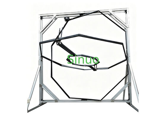
Modular frame assembled with standard industrial aluminum profiles; diagonal triangular bracing enhances structural rigidity. Base feet are pre-drilled for expansion bolt anchoring to prevent tipping. Inner clear span ≥1600 mm to accommodate maximum 1500 mm wheelbase UAV lateral installation; overall height controlled below 2.8 m.

Inner Three-Axis Rotating Frame

Z-axis (Vertical Axis): Outermost rotating joint, driving middle frame, inner frame and payload for full 360° vertical rotation. Heavy-duty slewing bearings ensure stable operation under 50 kg eccentric load.

Y-axis (Longitudinal Axis): Middle U-shaped hinged frame sized for 1000~1500 mm wheelbase aircraft with full-range horizontal rotation.

X-axis (Transverse Axis): Innermost fixture mounting bracket; UAV fixed on X-axis end to achieve full 360° roll around its lateral axis.

The three-layer frame hinged layout is consistent with the actual structure. The hollow frame design reduces weight while providing wiring channels, and the cables are internally protected. A conductive slip ring design is adopted.

Custom Fixtures

Standard array mounting holes on X-axis end face paired with adjustable telescopic fixtures for quick positioning and fixing of UAVs at 1000/1200/1500 mm wheelbase.

Drive & Control Hardware
  • Independent high-precision servo motors and planetary reducers installed on each of three axes to achieve 0.1° angular resolution
  • Freestanding electrical cabinet integrated with servo drivers, PLC master controller, power supply and circuit breakers, featuring multi-level protection against overload, overtravel and emergency stop
  • High-precision angular velocity sensors mounted on each axis for real-time data feedback to upper computer
Optional Upper-Computer Software
Core Functions
  • Programmed attitude control: preset fixed angles, constant/variable speed rotation, sine swing and custom motion trajectories for automatic test execution
  • Real-time data acquisition: synchronous recording of three-axis angle and angular velocity complying with ±0.2°/s accuracy requirement
  • Data storage & export: auto-save raw test data, export to Excel and generate real-time time-domain curves
  • Safety interlock: over-range emergency stop, soft limit protection and fault pop-up alarm to avoid UAV collision damage
Operating Environment

Windows-based desktop software communicating with control cabinet via USB/Ethernet; intuitive graphical interface without complicated programming required for regular testing.

Application Fields
  • Closed-loop simulation and debugging of UAV flight control algorithms
  • Calibration of airborne inertial sensors including gyroscopes and accelerometers
  • Reliability testing of power and stabilization systems under full-attitude conditions
  • Full-attitude environmental simulation for UAV R&D at research institutes
Installation & Acceptance Criteria
  • Install on flat concrete floor with leveled anchored base; final overall height ≤2.8 m after setup
  • No-load and full-load (50 kg) acceptance test: smooth 360° rotation without jamming; angular resolution and angular velocity accuracy fully meet specification
  • Full-function joint debugging of supporting software with qualified trajectory operation, data logging and report export
UAV Three-Axis Rotation Test Bench showing aluminum frame structure and rotating mechanism
Recommended Products
Products
PRODUCTS DETAILS
UAV Three-Axis Rotation Test Bench UAV Calibration Turntable with 360° Continuous Rotation
MOQ: 1
Price: Negotiable
Standard Packaging: Plywood Case
Delivery Period: 30 Days
Payment Method: T/T
Supply Capacity: 10 Sets Per Month
Detail Information
Place of Origin
China
Brand Name
Sinuo
Certification
Calibration Certificate (Cost Additional)
Model Number
SNW02
Test Station:
Single Station
Control Mode:
PLC + Touchscreen
Applicable UAV Wheelbase:
1000 Mm ~ 1500 Mm
Drive System:
Servo Motor + Precision Reducer
Rated Load:
50 Kg (aircraft + Fixture)
Rotation Range:
0~360° Unlimited
Angular Control Resolution:
≤0.1°
Angular Velocity Accuracy:
±0.2°/s
Minimum Order Quantity:
1
Price:
Negotiable
Packaging Details:
Plywood Case
Delivery Time:
30 Days
Payment Terms:
T/T
Supply Ability:
10 Sets Per Month
Highlight

360° Continuous Rotation Test Bench

,

UAV Three-Axis Rotation Test Bench

Product Description
UAV Three-Axis Rotation Test Bench UAV Calibration Turntable with 360° Continuous Rotation
Product Overview

This test bench is a custom-built precision XYZ three-axis 360° continuous rotation turntable developed for flight controller calibration, inertial component calibration and full-attitude simulation testing of medium-to-large multi-rotor UAVs with wheelbase from 1000 mm to 1500 mm.

The rated load capacity is 50 kg for complete UAV units; all three axes support unlimited continuous rotation of 0~360°, with angular resolution of 0.1° and angular velocity measurement accuracy of ±0.2°/s.

Controlled by PLC with touchscreen operation, the equipment is available with optional upper-computer measurement & control software to realize full-process management including programmed attitude control, data acquisition and curve analysis via PC.

Constructed with aluminum profile outer frame and lightweight high-strength inner rotating frame, the open mounting space enables quick clamping of UAVs with different wheelbases, applicable for laboratory R&D verification, third-party inspection and factory outgoing inspection.

Main Technical Specifications
No. Item Specification
1 Control Mode PLC + touchscreen; optional upper-computer control via PC
2 Station Single station
3 Applicable UAV Wheelbase 1000 mm ~ 1500 mm
4 Drive System Servo motor + precision reducer
5 Rated Load 50 kg (aircraft + fixture), 1.2 times overload safety margin (max 60 kg)
6 Rotation Range for X/Y/Z Axes 0~360° unlimited continuous rotation per axis
7 Angular Control Resolution ≤0.1°
8 Angular Velocity Accuracy ±0.2°/s
9 Overall Max Height ≤2.8 m
10 Frame Structure Vertical aluminum outer frame + hinged inner three-axis rotating rack
Mechanical Structure
Outer Fixed Support Frame

Modular frame assembled with standard industrial aluminum profiles; diagonal triangular bracing enhances structural rigidity. Base feet are pre-drilled for expansion bolt anchoring to prevent tipping. Inner clear span ≥1600 mm to accommodate maximum 1500 mm wheelbase UAV lateral installation; overall height controlled below 2.8 m.

Inner Three-Axis Rotating Frame

Z-axis (Vertical Axis): Outermost rotating joint, driving middle frame, inner frame and payload for full 360° vertical rotation. Heavy-duty slewing bearings ensure stable operation under 50 kg eccentric load.

Y-axis (Longitudinal Axis): Middle U-shaped hinged frame sized for 1000~1500 mm wheelbase aircraft with full-range horizontal rotation.

X-axis (Transverse Axis): Innermost fixture mounting bracket; UAV fixed on X-axis end to achieve full 360° roll around its lateral axis.

The three-layer frame hinged layout is consistent with the actual structure. The hollow frame design reduces weight while providing wiring channels, and the cables are internally protected. A conductive slip ring design is adopted.

Custom Fixtures

Standard array mounting holes on X-axis end face paired with adjustable telescopic fixtures for quick positioning and fixing of UAVs at 1000/1200/1500 mm wheelbase.

Drive & Control Hardware
  • Independent high-precision servo motors and planetary reducers installed on each of three axes to achieve 0.1° angular resolution
  • Freestanding electrical cabinet integrated with servo drivers, PLC master controller, power supply and circuit breakers, featuring multi-level protection against overload, overtravel and emergency stop
  • High-precision angular velocity sensors mounted on each axis for real-time data feedback to upper computer
Optional Upper-Computer Software
Core Functions
  • Programmed attitude control: preset fixed angles, constant/variable speed rotation, sine swing and custom motion trajectories for automatic test execution
  • Real-time data acquisition: synchronous recording of three-axis angle and angular velocity complying with ±0.2°/s accuracy requirement
  • Data storage & export: auto-save raw test data, export to Excel and generate real-time time-domain curves
  • Safety interlock: over-range emergency stop, soft limit protection and fault pop-up alarm to avoid UAV collision damage
Operating Environment

Windows-based desktop software communicating with control cabinet via USB/Ethernet; intuitive graphical interface without complicated programming required for regular testing.

Application Fields
  • Closed-loop simulation and debugging of UAV flight control algorithms
  • Calibration of airborne inertial sensors including gyroscopes and accelerometers
  • Reliability testing of power and stabilization systems under full-attitude conditions
  • Full-attitude environmental simulation for UAV R&D at research institutes
Installation & Acceptance Criteria
  • Install on flat concrete floor with leveled anchored base; final overall height ≤2.8 m after setup
  • No-load and full-load (50 kg) acceptance test: smooth 360° rotation without jamming; angular resolution and angular velocity accuracy fully meet specification
  • Full-function joint debugging of supporting software with qualified trajectory operation, data logging and report export
UAV Three-Axis Rotation Test Bench showing aluminum frame structure and rotating mechanism
sitemap |  Privacy Policy | China Good Quality Electrical Appliance Testing Equipment Supplier. Copyright © 2019-2026 Sinuo Testing Equipment Co. , Limited . All Rights Reserved.