

|
| MOQ: | 1 |
| Price: | Customized |
| Standard Packaging: | Plywood |
| Delivery Period: | 10 Days |
| Payment Method: | L/C, T/T |
| Supply Capacity: | 20 Sets Per Month |
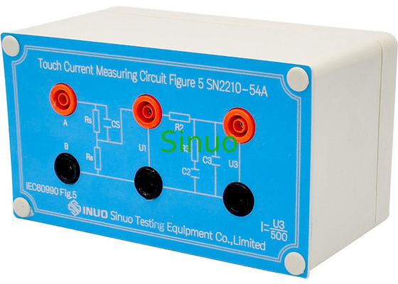
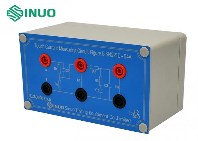
IEC 60335-1 Article 13 Power Supply Capacity Touch Current Measurement Circuit Figure 4
Product information:
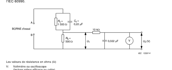
The test network complies with the measurement network requirements of IEC 60335-1 Article 13, IEC 60065: 2014 Article 9.1.1.2 b) and Annex D, Figure D.1, and IEC 60990 Figure 4 - Measurement network, touch current weighting for sensory or startle response.
The network is easy to use, simple to operate, the power transfer switch is made separately (see IEC60990 Figure 6, this device does not include), which solves the shortcomings of insufficient power capacity of the previous machine, and can test products with higher power.
Preparation:
Before the test, you will need the following equipment:
Scope x1
Double or tenfold voltage probe x1
Power supply x1 (test voltage or frequency, adjust or change voltage or frequency as needed)
Test Method
1. Adjust the power supply to output the desired test voltage and frequency, and then insert the input terminal of the touch current test transfer switch into the power supply. (Do not turn on the electricity when the network is not connected).
2. Insert the sample into the output of the touch current test transfer switch.
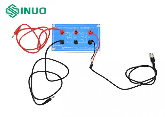
3. The B port of the touch current test switch is connected with the B port of the touch current measurement circuit.
4. Connect port A of the touch current measurement circuit to the place where the touch current is required. When testing a network adapter, connect port A to the output or housing of the adapter.
5. Clip the probe on the U1 or U2 terminals according to test requirements.
6. Turn on the power supply, put the switch "N" in the on position, the positive phase is placed in the positive phase position, and the switch line "G" is placed in the on position to check whether the tested sample is normally energized and whether there is a waveform on the oscilloscope.
7. After the sample is worked, according to the standard requirements, in the "positive phase," "inverted phase," "N line," "N line off," "G line off," "G line on" and other different modes, the voltage U1 and U2 are directly read with the oscilloscope, and the electric shock current is equal to the peak value of U2 and divided by 500.
Notice
During the test, it is necessary to pay attention to safety because you can touch some terminals.
According to the IEC 60990 standard, the power supply must be isolated, and the zero and ground wires must be connected together. If the voltage exceeds 2V, such as 220V power supply, the difference between the zero line and the ground line is more than 100V, then the zero line and the ground line must be connected together.
Please pay attention to the polarity of the power supply when testing. The fire wire must be connected to the L terminal of the contact current test switch. There is a risk of electric shock if the connection is wrong.
Connect the oscilloscope, test the sample, then connect the power after b-terminal line, and do not connect the test line when the power is connected.
|
|
| MOQ: | 1 |
| Price: | Customized |
| Standard Packaging: | Plywood |
| Delivery Period: | 10 Days |
| Payment Method: | L/C, T/T |
| Supply Capacity: | 20 Sets Per Month |
IEC 60335-1 Article 13 Power Supply Capacity Touch Current Measurement Circuit Figure 4
Product information:
The test network complies with the measurement network requirements of IEC 60335-1 Article 13, IEC 60065: 2014 Article 9.1.1.2 b) and Annex D, Figure D.1, and IEC 60990 Figure 4 - Measurement network, touch current weighting for sensory or startle response.
The network is easy to use, simple to operate, the power transfer switch is made separately (see IEC60990 Figure 6, this device does not include), which solves the shortcomings of insufficient power capacity of the previous machine, and can test products with higher power.
Preparation:
Before the test, you will need the following equipment:
Scope x1
Double or tenfold voltage probe x1
Power supply x1 (test voltage or frequency, adjust or change voltage or frequency as needed)
Test Method
1. Adjust the power supply to output the desired test voltage and frequency, and then insert the input terminal of the touch current test transfer switch into the power supply. (Do not turn on the electricity when the network is not connected).
2. Insert the sample into the output of the touch current test transfer switch.
3. The B port of the touch current test switch is connected with the B port of the touch current measurement circuit.
4. Connect port A of the touch current measurement circuit to the place where the touch current is required. When testing a network adapter, connect port A to the output or housing of the adapter.
5. Clip the probe on the U1 or U2 terminals according to test requirements.
6. Turn on the power supply, put the switch "N" in the on position, the positive phase is placed in the positive phase position, and the switch line "G" is placed in the on position to check whether the tested sample is normally energized and whether there is a waveform on the oscilloscope.
7. After the sample is worked, according to the standard requirements, in the "positive phase," "inverted phase," "N line," "N line off," "G line off," "G line on" and other different modes, the voltage U1 and U2 are directly read with the oscilloscope, and the electric shock current is equal to the peak value of U2 and divided by 500.
Notice
During the test, it is necessary to pay attention to safety because you can touch some terminals.
According to the IEC 60990 standard, the power supply must be isolated, and the zero and ground wires must be connected together. If the voltage exceeds 2V, such as 220V power supply, the difference between the zero line and the ground line is more than 100V, then the zero line and the ground line must be connected together.
Please pay attention to the polarity of the power supply when testing. The fire wire must be connected to the L terminal of the contact current test switch. There is a risk of electric shock if the connection is wrong.
Connect the oscilloscope, test the sample, then connect the power after b-terminal line, and do not connect the test line when the power is connected.

